
BK29 Series
High-Current, Optocoupler-Enhanced Linear Regulators
BK29 Series overview
BK29 is a series of low-noise, switching-free optocoupler-enhanced linear voltage regulators that use Polaris Semiconductor’s patented circuit topology. The devices consist of a high-current MIC29152 LDO co-packaged with Polaris Semiconductor high-efficiency optocoupler chips. This offers high PSRR, low ground current, and high output-current performance combined with device efficiencies that are typically 1.2× to >2× greater than a conventional LDO. The regulators are also tolerant to TID radiation levels up to 200 krad(Si) and have flight heritage aboard the International Space Station.
The BK29 series is available in a range of input and output configurations to suit various applications. The devices have adjustable voltage outputs and are available in multiple configurations addressing voltage ranges of 1.2–2 V, 2–4 V and 4–5 V. Polaris ELRs improve efficiency by connecting LEDs within our optocouplers in electrical series with the LDO within the package. Therefore, the minimum input voltage is greater than the output voltage by an amount depending on the number of LEDs in series. In chips ending with “V”, the optocoupler configuration can be set by the pin connections of the package. Configurations with LED series string lengths of 1, 2, 4 and 5 are labeled “L”, “M”, “H” and “E”, respectively. All the chips can also be operated as conventional LDOs by simply shorting two pins together to bypass the LEDs.
Base LDO: MIC29152. Every device can also be operated as a conventional LDO by shorting two pins.
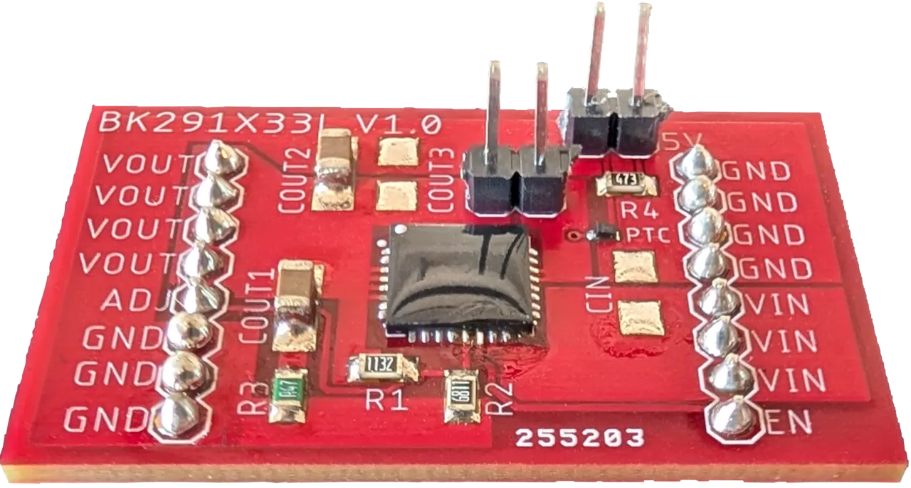
Device configurations
| Device | Nominal Vout range | Iin @ Iout = 100 mA | Min Vin @ Iout = 100 mA | QFN package |
|---|---|---|---|---|
| BK291D18V | 1.2 V – 2 V | 74 mA (L) 59 mA (M) | Vout + 1.4 V (L) Vout + 2.8 V (M) | QFN-28 · 6×6×0.8 mm |
| BK291D33L | 2 V – 4 V | 87 mA (L) | Vout + 1.4 V (L) | QFN-32 · 7×7×0.8 mm |
| BK291D33V | 2 V – 4 V | 75 mA (M) 59 mA (H) | Vout + 2.8 V (M) Vout + 5.5 V (H) | QFN-32 · 7×7×0.8 mm |
| BK291D50E | 4 V – 5 V | 60 mA (E) | Vout + 7.0 V (E) | QFN-32 · 7×7×0.8 mm |
- All devices are adjustable down to Vout = 1.2 V.
- Iin is typical input current after device turn-on.
- Product IDs ending in “V” are configurable for one of two input-voltage ranges, selectable via board-level pin connections.
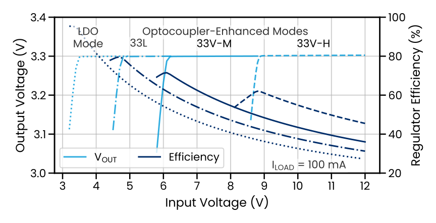
Applications
- Clean Analog Supply Requirements
- Post-Switching Power Supply
- Rad-Tolerant Space Power Supply
- Battery-Powered Systems
- Portable Electronics
- Data Converters
Technical documentation
Application notes, white papers, and spotlights covering the BK29 series.
Datasheets and SPICE models ship with a sample request — or email [email protected].
Ready to design it in?
Request evaluation samples, detailed datasheets, and SPICE models — an engineer answers, not a sales funnel.